- About Us
- Committees
- SUT Houston Branch Executive Committee
- Offshore Site Investigation and Geotechnics (OSIG)
- Subsea Engineering and Operations - Atlantic (SEO-Atlantic)
- Group on Environmental Forces (GEF)
- Robotics & Automation (R&A)
- Marine Renewable Energy Committee (MREC)
- Education Committee
- SUT Young Professionals
- Advisory Committee
- School Touring Committee
- Women in Industry
- Become a Member
- Student Chapters
- Mentoring Program
- Learning Programs
- Events
- News
- 2023
- 2022
- 2021
- 2020
- SUT-US Champagne & Conversation Series Edition 5
- SUT-US Makes Its 15th Appearance at Subsea Tieback Forum & Exhibition
- SUT-US Brings Its School Touring Program to the Largest School District in Houston
- SUT-US Brings Its School Touring Program to the Largest School District in Houston
- SUT-US Champagne & Conversation Series Edition 6
- Making History - SUT-US Elects its First Woman Chair and President
- Scholarship Awards Ceremony 2020
- 2019
- 2018
- 2017
- Dr. Medina-Cetina Presents at European Geosciences Union (EGU) GIFT Workshop
- 'Geology Rocks' 500 at Thornton Middle School
- SUT-SEO Presents Subsea Awareness Course
- Society for Underwater Technology Awards Six at Scholarship Reception
- School Touring Reaches Opal Hamilton Students
- Passion Runs Deep in the Subsea Engineering Society
- Galveston Student Chapter Presents First Short Course
- Promoting A Welcoming Environment, SUT Actively Combats Discrimination and Sexual Harassment
- Subsea Awareness Course Offer its Expertise to Mexico's Industry Professionals
- SUT-US Gifts this Academic Year's Annual Sponsorship Checks to its Student Chapters
- SUT-USA Launched the New Committee: Group on Environmental Forces
- SUT-US Launches a New Student Chapter at Rice University
- 2017-2018 Scholarship Awards Ceremony
- 2016
- Press Releases
- Subscribe
Underwater Visualisation A Personal View
Articles and Publications
Introduction
1. This short paper gives personal view of the developments in underwater visualisation over the last 20 years based on its practical application in the marine salvage field.Background
2. Advances in computing power and sonar technologies, often lead by the military, but more recently by the offshore industry have seen significant advances in mans ability to visualise the underwater domain.3. The last 20 years in particular have seen some dramatic improvements in the clarity and accuracy of images produced.
History
4. My interest in the subject begins in 1992, when shortly after I had joined the UK Ministry of Defence as a Salvage and Mooring Officer, after 15 years in the Merchant Navy, I was involved in the location and recovery of a military aircraft that had ditched in the North Sea. At that time the primary method of locating aircraft in shallow water was by using a fishing vessel to scour the seabed to try and pinpoint the wreckage and then to bring in a moored vessel equipped with an underwater surface managed pan and tilt camera and divers to recover it. In this case pieces of the wreckage were located by the fishing vessel and a Salvage and Mooring vessel, with a dive team, a commercially hired Remotely Operated Vehicle (ROV), with a bolt on Ultra Short Base Line (USBL) acoustic tracking system was deployed to plot the wreckage and attempt to recover it. Over a 3 month period the wreckage was eventually plotted over 500m x 10,000m area, by frequently 4 point mooring the vessel and sweeping the ROV around the vessel to the maximum relative range of the USBL.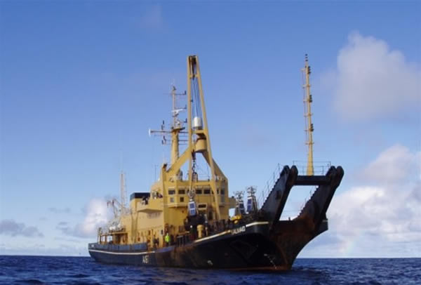
Salvage and Mooring Vessel RMAS SALMAID
Development
5. It became clear that emerging technologies could help reduce the time and expense of locating aircraft and assisting in salvage activity in turbid water situations. During the next few year I was involved in a number of marine salvage tasks including aircraft recoveries, ship wreck investigations and port clearance tasks which gave an opportunity to utilise and develop some of these developing technologies. These included side scan sonar, various forms of multi-beam sonar, laser line scan, all with various forms of geo-referencing. In all cases the key difficulty in developing a clear and accurate image, was to mosaic the various sonar or side scan passes, into a single coherent overview.SS Richard Montgomery Survey
6. In 1995 whilst working for UK Department for Transport who required a detailed survey of the SS Richard Montgomery , the opportunity arose to link a vessel mounted high resolution multi beam sonar with a high update rate (Real Time Kinetic (RTK)) geographic reference system. This allowed the production of an accurate and geo-referenced wide area bathymetric chart, showing for the first time the wreck and impact it was having on the adjoining seabed.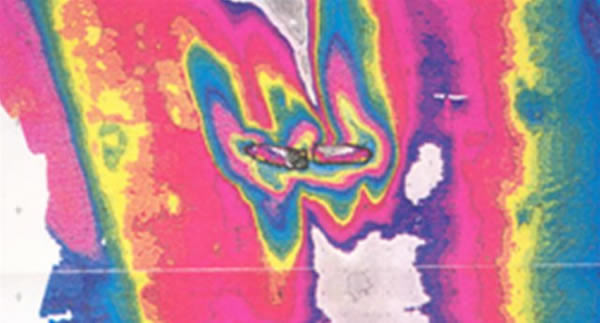
1995 SRD SVS - Bathymetric images of the SS Richard Montgomery Courtesy of the UK Department for Transport
HMS Royal Oak
7. In February 1996, a similar survey to that conducted on the SS Richard Montgomery was conducted on HMS Royal Oak in Scapa Flow. The resultant image was processed onboard the survey vessel and used to fly an embarked "work class" ROV around the wreck, aligning the images taken by the ROV to the 3 dimensional plot produced by the SRD SVS/RTK process. The ROV was also equipped with a shot blasting system and thickness gauge, with which it was intended to take thickness measurements of the hull, unfortunately the ROV was unable to hold the thickness gauge steady enough to gain accurate and repeatable readings.Holy Loch
8. Between 1961 and 1992, Holy Loch was the site of the United States Navy's "FBM Refit Site One". It was the home base of Submarine Squadron (SUBRON) 14, part of Submarine Force, U.S. Atlantic Fleet. Following the withdrawal of the US vessels, which included a floating dry dock, submarine tender and associated vessels, the Ministry of Defence, wanted to return the Holy loch waters, then under a dockyard port order, to the local conservancy authority. However, before accepting the waters the local conservancy authority sought assurance that the seabed was free of debris and contamination. An initial side scan survey had indicated that there was some debris in the loch, however a detailed multi-beam survey, followed by an a ROV visual survey in 1996, revealed significant amounts of debris, some up to 6 meters above the seabed. Given the depth and entrapment hazard the scrap represented to divers, a diver less intervention system was developed.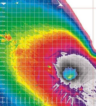
A multi-beam image of the seabed of the holy loch showing the seabed indentations made by the moored dry-dock and vessels and the piles of debris adjacent to them ? Image Crown Copyright
9. A clearance programme was begun, commencing in early 1997, with a pilot phase. This utilised the SRD SVS/RTK system to accurately manoeuvre a crane mounted on a barge equipped with a either a grab or an electro magnet. Due to environmental considerations the works could only be undertaken during the winter months. The system was later improved with the addition of a SRD developed scanning sonar which tracked the grab/magnet in the water column. The seabed was broken up into 25m square boxes, which were then methodically cleared one square meter at a time. On completion of each 25 meter square box clearance, a sled containing 4 cameras was manoeuvred over the area to provide a photo-graphic record, to speed up productivity, a sonar tracked ROV was later utilised for this task.
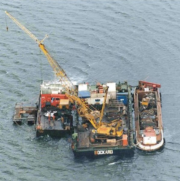
The Holy Loch main phase recovery barge, with crane and sonar control cabins wash down barge and scrap transfer barge ? Image Crown Copyright
10. The recovery operations went on for 3 winter seasons eventually recovering some 7,000 tonnes of scrap metal, along with over one thousand gas cylinders, and 3 sunken landing craft all of which was recycled.
MV Derbyshire
11. I participated in the two, UK Department for transported funded surveys of the wreck of the MV Derbyshire, the UK?s largest peacetime loss. During the main 53 day second survey I was the UK Governments sole representative, as well as being responsible for the identification team and the transfer of data from the contractors to the UK DfT. This survey at approximately 4200 meters water depth involved a totally different set of techniques and tools to build an over view of the wrecks site.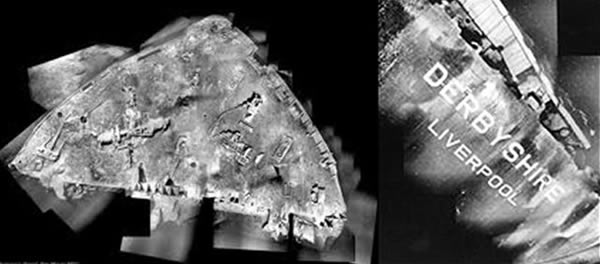
Images of the MV Derbyshire built up by hand and eye from images taken by the Argo camera sled
Woods hole Oceanographic institute (WHOI) were contracted by the UK DfT and the EU to undertake a forensic survey of the Wreck of the MV Derbyshire to determine the cause of her sinking. Three assessors were appointed to review the data recovered. The survey was undertaken in several phases; firstly the survey vessel hull mounted sonar was used to determine the overall bathymetry in the vicinity of the wreck. Then a long base line (LBL) acoustic tracking system was deployed. WHOI then deployed there ?Argo? towed sled which used a digital camera and high power lighting to take images every 13 secs as it was towed over the wreck. These image were then up loaded and mosaicing process used to produce larger images of ship sections such those shown above. After the visual images (approx 132000) had been collected, the ?Jason? ROV was deployed to look at specific areas of interest, and where necessary to take high resolution images of fracture faces.
HMS Royal Oak
After the initial survey of the wreck of the Royal Oak in 1996, a programme of oil removal was instigated. A further survey was undertaken in 2006 by a company called ADUS, who used a hull mounted multi-beam sonar, and RTK navigation input combined with body imaging software to develop true 3D fly through models, see image below. The also under took a similar survey of the SS Richard Montgomery .When compare with the 1995 image from the Richard Montgomery survey, this 2006 images shows how quickly the technology is developing.
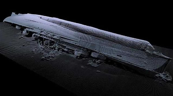
3D Image of HMS Royal Oak in Scapa Flow ? Image is Crown copyright
B159
In 2007 as part of the Arctic Military Environmental Cooperation Programme , the UK Government funded the survey of the nuclear fuelled Russian submarine B159 in the waters north of Murmansk, which had sunk in approx 250 meters water depth whilst under tow in August 2003, with the loss of nine crew members. The project was managed by the UK MoD salvage department, utilising the NATO Underwater Research Centre (NURC) vessel "Alliance", the NATO Submarine Rescue Service ROV and ADUS to provide the 3D dimensional imaging. It had been hoped to deploy a RTK beacon on Kildin Island, but last minutes security issues prevented this and so differential signals where provided via satellite, which provided something of a challenge at such high latitudes. Due to the depth the ADUS sonar head was mounted on the ROV and high update rate hydro-acoustic positioning system used to track the ROV with sufficient accuracy to allow the production of a 3D model of the submarine, two floatation devices and the surrounding seabed. Whilst onsite the team undertook radiation measurements and samples and recovered a Russian ROV that had been lost during an earlier attempt to survey vessel. Ironically it had ingested the submarines ensign in one of its thrusters.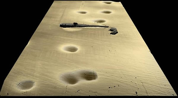
3D images of B139 and surrounding seabed in 250m water depth - Image is Crown copyright
Autonomous Underwater Vehicles
In the last few years my Department has used Hydroid Remus 100 Autonomous Underwater Vehicles (AUV) operated by the UK Royal Navy to locate relatively small objects on the seabed. These are fitted with the high resolution side scan sonar and fly close to the seabed giving high quality data that would be hard to achieve using traditional towed side scan. Once deployed the REMUS runs a pre-programmed route collecting data, which is subsequently downloaded and analysed.
UK RN personnel deploying a Remus 100 AUV
HMS Royal Oak Today
During Dec 11, a further 3D survey was under taken on the hull of The Royal Oak, again using the hull mounted multi-beam sonar and an RTK navigation system, this time by a company called Net Survey. The results of this survey are being used to compare with data from previous 3D surveys to determine if any changes have taken place on the wreck over the intervening periods between surveys. The ability to produce photograph like images of a wreck and detect small changes in a hull shows how far multi beam systems have advance within a short time.by James Ward MBE January 5, 2012
James Ward MBE
Currently holds the position of Deputy Team Leader Salvage and Operation, with the Salvage and marine Operations (S&MO) Project Team, part of the Ministry of Defences, Defence Equipment and Support. He is based in Bristol, England.Currently he is the Assistant Director responsible for Salvage and related Marine Operations, where he is directly responsible for the two MOD marine salvage units and the MOD in water maintenance and repair desk, providing tri-service worldwide marine salvage and in water maintenance and repair support and expertise.
As a Master Mariner he joined the MOD in 1991, following 15 years working in the commercial maritime industry. Since joining the MOD he has a variety of jobs within the Salvage and Mooring area. He qualified as a commercial diver in 1999 and was awarded an MBE in 2003 for his work on maritime salvage and protection of the maritime environment. Key achievements include:
- Project Manager for the recent salvage of HMS Endurance off Chile
- Project Director for the ?world leading? survey of the Russian Submarine B159.
- Project Manager for the Heavy lift of HMS NOTTINGHAM in Sydney harbour
- Project Manager for the 1st UK full ROV recovery of a fragmented fast jet from the sea.
- Project Manager of the preliminary research, initial surveys, temporary patching and pilot oil extraction operation of HMS Royal Oak in Scapa Flow.
- Project Officer during phase 1 of the return to MV Derbyshire. Sole UK Government Representative, data manager and leader of the identification team during the 52-day phase 2 of the DOT sponsored return to MV Derbyshire.
- Project Manager of the environmental baseline studies, approvals procedure and initial recovery phases of the multi-million pound Holy Loch debris clearance project.
- Acted as senior Salvage Master and Project Director, during high profile salvage incidents, recent examples including the 4 month recovery of Tornado jet from the sea adjacent to Torness power station, emergency towing advice to disabled vessels, the refloating of a Type 23 frigate and the recovery of a ditched Merlin helicopter.
Sources and Links
http://www.dft.gov.uk/mca/1995_survey_report_montgomery.pdf
http://www.dft.gov.uk/mca/ops-row-mca_rm_survey_2005_final_report.pdf
Upcoming Events 2024
| Apr 15 - Jun 3 | 2024-2025 SUT-US Scholarship Applications |
| May 6, Mon | May Networking Event - Renewable Connection |
| May 9, Thu | SPE Hiring Event |
| May 15, Wed | Connect, Collaborate, Succeed! Young Professionals Networking |
| May 22 - 23 | EAGE/SUT Workshop on Integrated Site Characterization for Offshore Renewable Energy |
| May 23, Thu | Boston Offshore Wind Drinks |
| Jun 6, Thu | SUT-US Networking Event |
| Jul 4, Thu | No Networking Event for the month of July |
| Aug 1, Thu | SUT-US Networking Event |
| Sep 5, Thu | SUT-US Networking Event |
Membership available for students, individuals and corporations


